Home Associative Quadruple Envelope

Associative Quadruple Envelope

Sold out
Sale price €598,00

Worlwide Shipping
We ship worldwide from our EU warehouse.


Dedicated Support
1-Year Warranty on every purchase.

Guaranteed Safe Checkout

Visa
Mastercard
American Express
Maestro
Union Pay
Apple Pay
Google Pay
Shop Pay
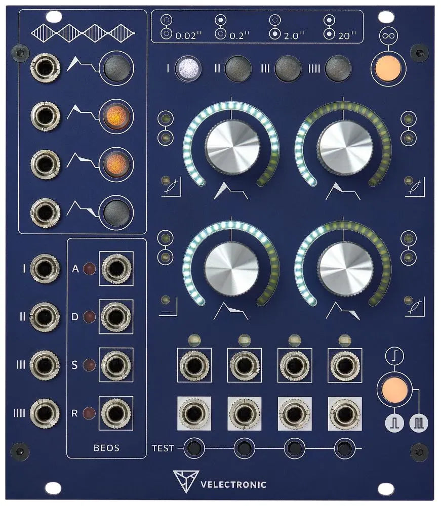
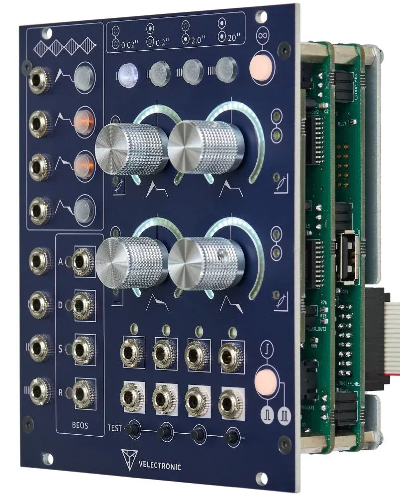
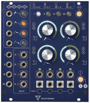
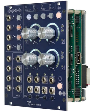
Quadruple envelope specialized for polyphonic and multitimbral systems. The module is very high quality manufactured and allows due to the endless encoders a very pleasant operation and switching between the individual envelopes.

Associative Quadruple Envelopes allows easy grouping of multiple envelopes, making it ideal for polyphonic and multitimbral patches. Each envelope can also be used as an LFO and is stable even at very high frequencies. Stages can be given different characteristics (linear, logarithmic, exponential) and their maximum amplitude can also be set. Assignable CV inputs can be applied to the parameters (duration, characteristic, amplitude) and the BEOS outputs can output gates or triggers either at the beginning or at the end of an envelope. BEOS outputs can therefore also be used to chain several envelopes.
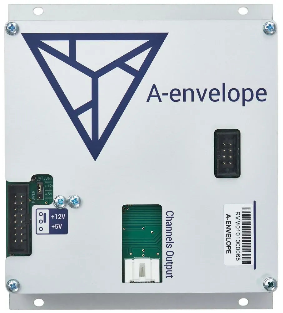
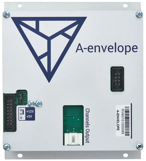
It is recommended to activate the +5 V switch to relieve the +12 V rail, otherwise 245 mA are consumed by the +12 V rail. When the +5 V switch is active, only 35 mA is consumed from the +12 V rail and 170 ma from the + 5 V rail (the current consumption on the -12 V rail is constant). If no +5 V rail is available, the high current consumption should definitely be taken into account when planning the case.

Association between channels

A-envelope allows to define channel groups, that shares configuration. This capability makes possible to define polyphonic configurations on the go
up to 4 voices, in a simple way.

Each channel allows to

  • Modulate every of the ADSR stages in time or shape (Exp, Lin, Log) independently.
  • Adjust the amount of modulation using the stage knobs when acting as attenuverters.
  • Controlling the duration of each stage from 0 to 20 seconds using the stage knobs.
  • Controlling the shape of attack, decay and release stages.
  • Controlling the level of the sustain stage.
  • Controlling the amplitude of the whole envelope.
  • Configure the input activation mode as Gate, Trigger or Re-Trigger.
  • Configure the channel in single, loop or auto-loop mode.
  • Configure the BEOS (Begin and/or End Of Stage) outputs for each stage.
  • Trigger the channel manually using the test button.

Loop & Auto Loop

If the Gate mode is activated, the envelope will be automatically relayed at the end while the input signal remains activated.

If
the Trigger mode is activated, the envelope will automatically
re-launch when it finishes after receiving a pulse. Receiving a new
pulse will stop the loop.

User interface

The user interface is meant to give a fast and direct access to every feature.

  • Instant visualization of each channel group thru the scale indicators and LED arches.
  • Direct monitoring of the signal and BEOS outputs thru specific LEDs.

Pulse / Gate

Selection of the entries work mode.

Input Jacks

Selection of the entries work mode.

Input Buttons

Trigger / gate buttons for the envelope manual start

Time ranges

Attack

The minimum amount of time is 400 microseconds, under this value the stage is omitted. The maximum amount of time is 20 seconds.

Decay

The
minimum amount of time is 400 microseconds, under this value the stage
is omitted and therefore, the maximum voltage for the attack becomes the
one defined by the sustain. The maximum amount of time is 20 seconds.

Sustain

The
minimum amount of time is 400 microseconds, under this value the stage
is omitted but the voltage level remains as a reference for the other
stages. The maximum amount of time is 20 seconds.

Release

The minimum amount of time is 400 microseconds, under this value the stage is omitted The maximum amount of time is 20 seconds.

Inputs

ADSR modulation inputs

The
ADSR modulation inputs accepts signals from -10 to 10 volts and a
bandwidth from DC up to 20kHz. The attenuverters associated to the
inputs can amplify/attenuate the input signal from 0 to x2.

ParameterValueInput impedance100kOhmsMaximum input voltage+/- 10 VoltsBandwidthDC to 20kHz

Trigger/Gate inputs

The trigger/gate inputs react to pulses of at least 2.5Volts and 50us.

ParameterValueInput impedance100kOhmsMinimum input voltage2.5 VoltsMinimum pulse duration50uS

Outputs

ADSR envelope outputs

The
ADSR envelope outputs have a voltage range of 0-10 volts, and a minimum
period time of 400 microseconds using only the Attack stage. The ADSR
envelope outputs are doubled to offer both direct and inverted outputs.
Both sets have the same characteristics.

ParameterValueOutput impedance1kOhmsOutput voltage0 - 10 Volts

The BEOS outputs

The BEOS (Begin-End Of Stage) outputs have a voltage range of 0 volts when inactive and 10 volts when active.

ParameterValueOutput impedance1kOhmsOutput voltage0 / 10 Volts

Power consumption

The power consumption it is been measured with all LEDs on.

The +5V jumper selected (Recommended)

  • +5v = 170 mA
  • +12v = 35 mA
  • -12v = 23 mA

The +12V jumper selected

  • +5v = 0 mA
  • +12v = 245 mA
  • -12v = 23 mA

Protection

  • Protection for human body model electrostatic discharge (ESD) of 2kV.
  • Power connector reverse protection.
  • Protection against power polarity inversion.

Working Temperature

  • Working ambient temperature from -20ºC to 70ºC.

Accuracy

  • The accuracy for all specified values is < 1%.

Dimensions

  • 22HP
  • 3U
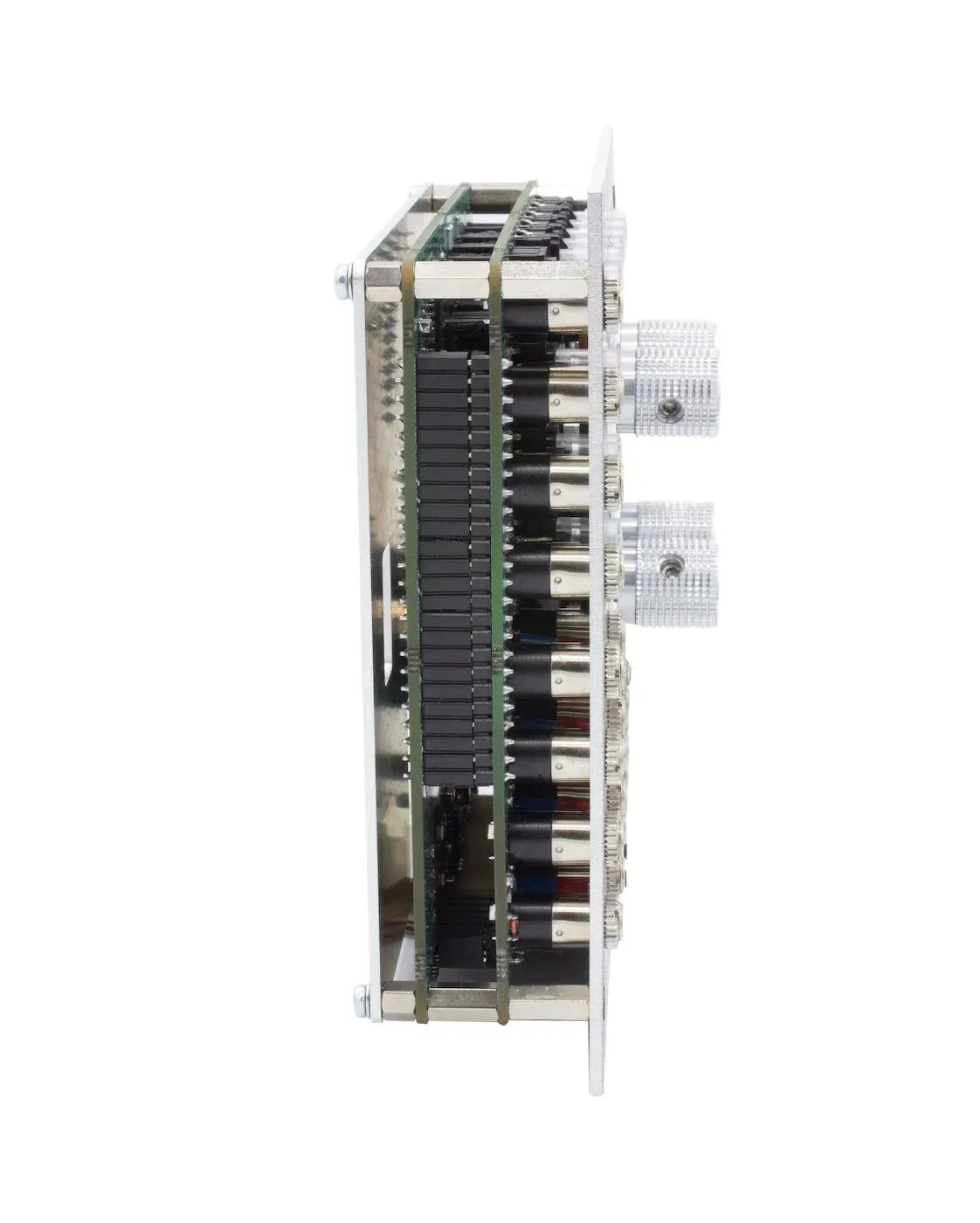
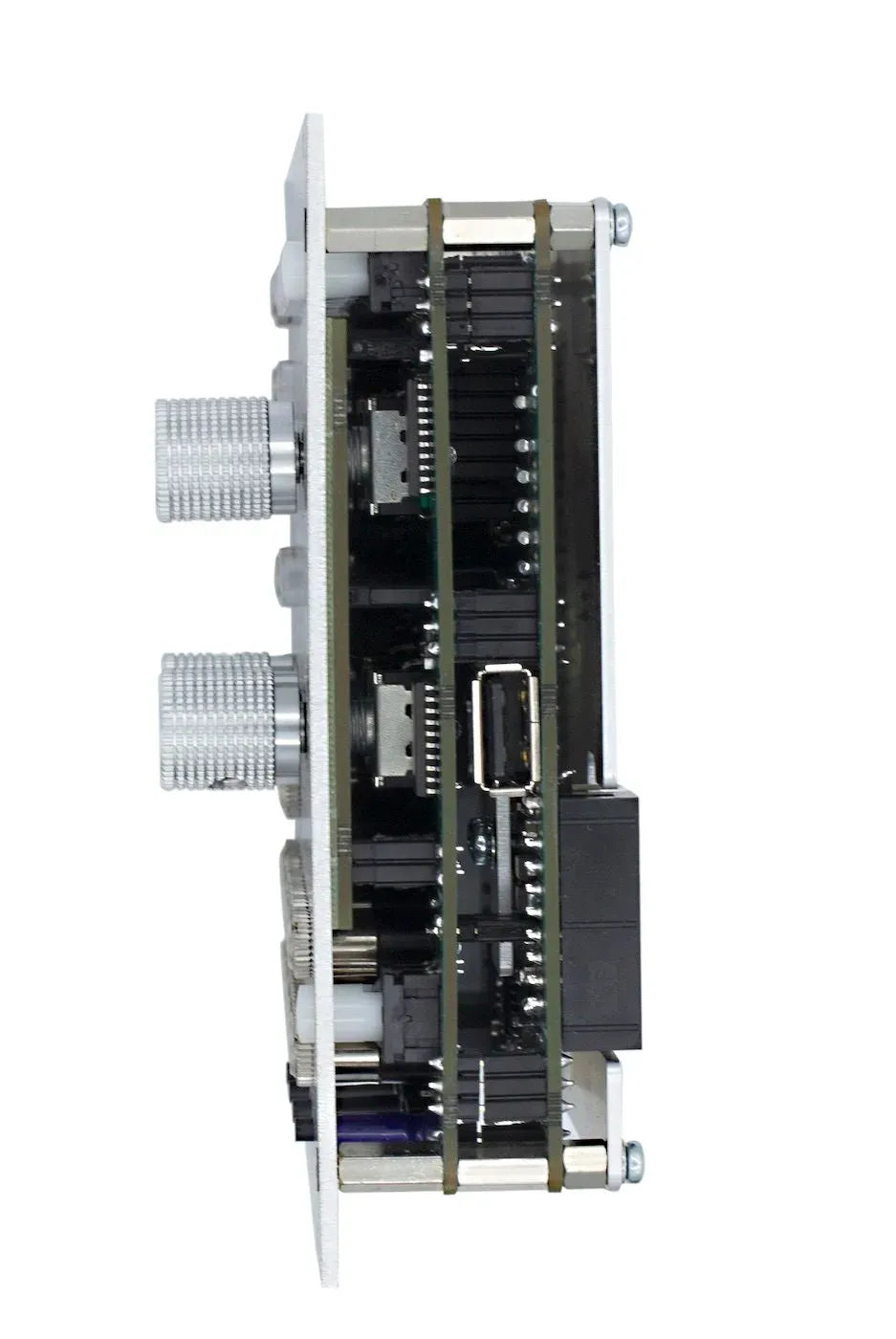
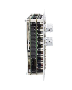
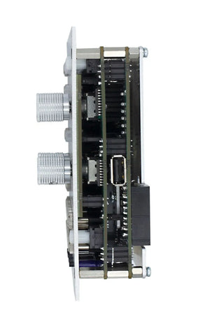
  • 38mm depth from the back of the panel to the power connector, including the connector.

Documentation

Here below you can find all the current available documents, including the one delivered with the module.

Firmware updates

Here below you can find all the available firmware update, including the one delivered with the module.

Update procedure

The A-envelope is provided with a USB A port, for firmware update purposes. Follow the steps to perform the update.

  1. Download from the firmware list the on you want to apply.
  2. Copy the downloaded file to at the root of your USB storage device.
  3. Rename the copied file to a-envgen.hex.
  4. Power off the module.
  5. Keep pressed the Attack modulation button.
  6. Power on the module.
  7. Now the module is in boot mode.
  8. The trigger and sustain modulation buttons will get enabled and the channel buttons will blinking waiting for a USB storage device.
  9. Plug the USB storage device in the module USB port.
  10. If everything is fine, the channel buttons will show the firmware update check progress.
  11. If the firmware is not been detected, the channel buttons will remain blinking and you will need to check the previous steps.
  12. If the firmware is not a valid, or is not suitable for this module, the release shape LED will start blinking.
  13. If the firmware update check succeeds, the channel button will turn off
    and the loop, trigger and sustain modulation buttons will get enabled.
  14. Push the loop button to proceed with the update.
  15. The channel buttons will show the firmware update progress.
  16. Once the update terminates, the module will restart.

Now you can enjoy the new features.

Reset to factory values procedure

Follow the steps to apply the factory default values.

  1. Power off the module.
  2. Keep pressed the Attack modulation button.
  3. Power on the module.
  4. Now the module is in boot mode.
  5. The trigger and sustain modulation buttons will get enabled and the channel buttons will blinking waiting for a USB storage device.
  6. Push the sustain modulation button to proceed with the factory default values recall.
  7. Push the trigger button to restart the module.

Now you can start using it again as came out from the box.